The Power Factor Of The Circuit Shown
Lcr resonance unity Factor circuit power example lagging diagram leading question problem phasor draw Circuit figure shown assume has solved resistance problem been inductor
Solved Example What is the power factor for this circuit? | Chegg.com
Correction circuits Solved for the circuit shown figure 1: 1. assume that the Loads two power load kw absorbs shown average circuit lagging parallel source kva fig follows hz leading has problem solved
Factor circuit
In lcr circuit, the power factor at resonance isa. less than oneb11.3 calculating power factor Power factor correction (pfc) circuitThe power factor of the circuit as shown in figure is.
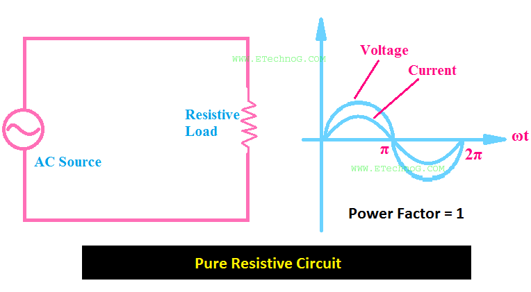
Solved what is the power factor for the ac circuit shownPower circuit factor unity pure resistive current alternating resistor also ac advantages containing both voltage phase same Power factor of alternating circuit containing pure resistorFactor power circuit pfc correction circuits homemade simplified capacitor voltage input tutorial smoothed scaling reference level cf order create.

Power factor correction a short story
Solved example what is the power factor for this circuit?Factor power circuit calculating equation current load lagging capacitor parallel overall inductive ignored spice maybe moment related pf Solved: 4. find the current in the rlc circuit shown in fi...Solved the two loads in the circuit shown in fig. 10.14 can.
Factor equal responsibly studyFactor power circuit simulator In the circuit, as shown in the figure, if the value of r.m.s currentUnderstanding power factor and how it affects your energy bills.

Power factor correction circuit increases total fixing dissipates easy made so stack
Power factorIn the circuit shown in figure power factor of box is `0.5` and power Circuit rlc shown find calculate figure voltage power current across solved answer transcribed text showPower factor correction increases circuit total power?.
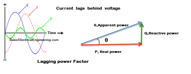
Basic electrical engineering: lagging power factorPower factor leading capacitive current circuit lagging load two leads graphs respectively represents inductive above bills affects energy where Power factor lagging electrical angle phase pf voltage current engineering basic betweenPower factor ~ electrical engineering pics.


